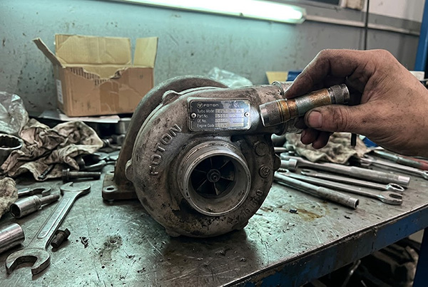
Choosing the wrong truck relay costs more than the part itself — it costs time, return shipping, and sometimes a truck sitting idle on a job site. Truck relays seem simple, but confusing coil voltage with contact voltage, trusting nameplate amps at face value, or swapping relays based on shape alone leads to burned circuits and frustrated customers.
A truck relay must match three independent specs before installation: the coil voltage that energizes it (typically 12V or 24V), the current rating appropriate for the actual load with a safety margin applied, and the correct terminal configuration for the circuit it controls. Verifying all three — not just one — prevents relay failure, wiring damage, and unnecessary replacement costs.
In our experience handling relay orders for HOWO, SHACMAN, FAW, FOTON and DONGFENG trucks, most relay-related returns trace back to one of these three areas. Below, I break down each spec in detail so you can confirm the right relay before committing to a bulk purchase or installing it on a truck.
Why Is Coil Voltage the Most Misunderstood Truck Relay Spec?
A customer orders a "24V relay" for a HOWO truck, installs it, and the relay either clicks weakly or burns out within hours. We see this pattern regularly, and it almost always comes down to confusing coil voltage with contact voltage — two completely different circuits inside the same relay.
The coil voltage is the voltage needed to energize the relay's internal electromagnet — the signal side. The contact voltage is the maximum voltage the relay's switching contacts can handle on the load side. A relay marked "24V coil / 28V contact" requires a 24V signal to activate, but its contacts can switch circuits up to 28V. These are not the same number, and treating them as interchangeable causes immediate failure.
What Happens When You Apply the Wrong Coil Voltage?
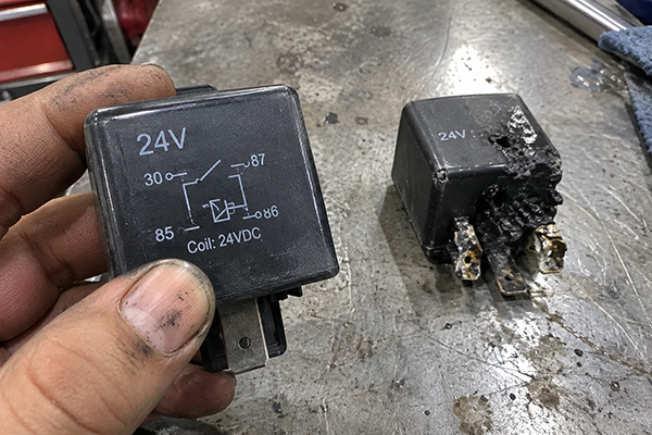
Every relay coil is designed for a specific voltage — commonly 12V or 24V in truck applications. Applying a voltage significantly higher than rated generates excessive current through the coil winding, overheating and eventually burning it out[1]. Applying too low a voltage produces insufficient magnetic force, meaning the relay either fails to close its contacts or closes them weakly, causing arcing and premature contact wear.
Most Chinese heavy trucks — HOWO, SHACMAN, FAW — run 24V electrical systems[2]. However, some auxiliary circuits, aftermarket accessories, or specific control modules may operate at different voltages. The relay coil must match the signal circuit voltage, not the main battery voltage assumed by the buyer.
How to Read Relay Voltage Markings Correctly
Relay bodies typically print voltage information, but the format varies across manufacturers:
| Marking Style | Meaning | Example |
|---|---|---|
| "24V" (single number, no qualifier) | Usually refers to coil voltage | Coil requires 24V DC to energize |
| "Coil: 24VDC / Contact: 28VDC" | Explicitly separated | Coil needs 24V; contacts rated up to 28V |
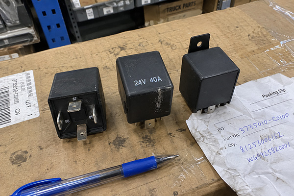
| "24V 40A" | Coil voltage + contact current rating | 24V coil; contacts handle up to 40A |
| No marking or partially worn text | Unknown — must verify with OE number or datasheet | Do not assume; test or cross-reference |
Key takeaway: When you see a single voltage on a relay, assume it describes the coil unless the label explicitly states otherwise. If in doubt, cross-reference the relay's OE number against the vehicle wiring documentation.
A Common Ordering Mistake We See
A pattern we encounter in our order consultations: a customer sourcing relays for a mixed fleet requests "24V relays" without specifying whether they mean coil voltage, system voltage, or contact voltage. We always ask for the OE number or the relay currently installed on the truck. This one clarification prevents the majority of voltage-related returns. If you are placing a bulk relay order, provide the OE number, truck model, and the specific circuit the relay controls — starter relay, fan relay, air conditioning relay, and so on. Each application may require a different relay even on the same truck.
How Should You Interpret Current Ratings on Truck Relays?
A relay stamped "40A" does not mean you can safely run 40 amps through it continuously in every application. This is the second most common source of relay failure we deal with, particularly for relays controlling motors, solenoids, and other inductive loads on heavy trucks.
Nameplate current ratings on truck relays represent nominal capacity under resistive load conditions at a specific temperature — usually around 20–25°C. Real-world truck applications involve inrush currents from motors and solenoids that can spike to 3–8× the steady-state draw, ambient temperatures inside engine compartments exceeding 80°C, and vibration that degrades contact integrity over time. To account for these factors, select a relay rated at 1.5–2× your expected steady-state load current[3].
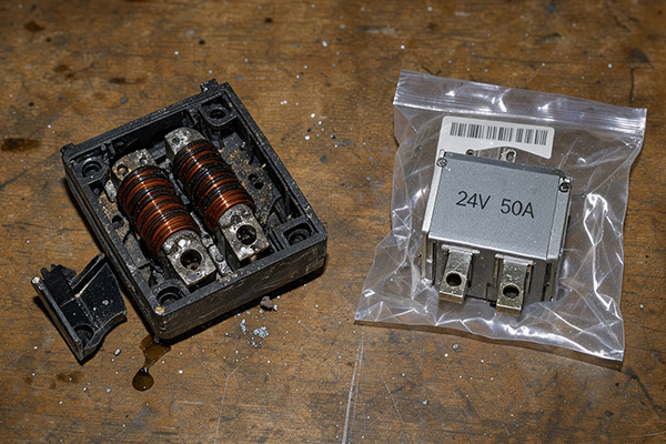
Why Nameplate Amps Are Not Real-World Amps
Relay manufacturers test and rate contact current under controlled laboratory conditions — typically with resistive loads (like heaters or lights) at room temperature[4]. Truck circuits rarely resemble those conditions. Here is what actually stresses relay contacts in the field:
- Inrush currents: An electric cooling fan motor with a 15A steady-state draw may pull 60–90A during startup. A relay rated at 20A will survive a few of these surges before its contacts weld together or pit beyond function[5].
- Ambient heat: Engine bay temperatures in tropical climates or during sustained heavy-duty operation can exceed 80°C[6]. Higher temperatures increase coil resistance and reduce contact capacity.
- Vibration and shock: Chinese heavy trucks operating on unpaved roads in Africa, Southeast Asia, or mining sites experience continuous vibration that causes relay contact bounce, generating micro-arcs that erode contact surfaces[7].
- Duty cycle: A relay that cycles on and off frequently (like a turn-signal flasher relay or an intermittent wiper relay) wears faster than one that stays energized for long periods.
Practical Derating Guidelines
I am not presenting these as laboratory-grade engineering specifications. These are practical rules we share with our customers based on patterns we have observed across thousands of relay orders:
| Load Type | Derating Multiplier | Example |
|---|---|---|
| Resistive (lights, heaters) | 1.25× steady-state current | 20A load → choose ≥ 25A relay |
| Inductive (motors, fans, solenoids) | 1.5–2× steady-state current | 20A load → choose 30–40A relay |
| High-cycle (flasher, intermittent wiper) | 1.5× + consider relay rated for high-cycle life | 10A load → choose ≥ 15A relay with documented cycle rating |
| Harsh environment (extreme heat, dust, vibration) | Add additional 20–30% margin on top of above | Adjust upward from the relevant baseline |
Practical example: If a SHACMAN truck's radiator fan motor draws 25A at steady state, do not order a 30A relay. Choose a 40A or 50A relay. The cost difference between a 30A and 50A relay is negligible compared to a roadside breakdown or a returned container of wrong parts.
What "Maximum" Really Means
Some relay datasheets list both a continuous rating and a maximum (peak) rating. The continuous rating is what the relay sustains indefinitely under test conditions. The maximum rating is typically a short-duration figure — sometimes only a few seconds. For truck applications, always size your relay selection against the continuous rating with the derating multiplier applied. Treat the maximum rating as a momentary tolerance, not an operating specification.
Why Doesn't the Same Relay Footprint Mean the Same Relay?
This is the third mistake we regularly encounter, and it is especially common in bulk orders: a buyer selects a relay because it physically fits the same socket, only to discover it has a different coil voltage, contact configuration, or current rating. Same footprint does not mean interchangeable.
Truck relays sharing the same physical dimensions and pin layout — such as the common ISO mini relay form factor[8] — can differ in coil voltage (12V vs. 24V), contact arrangement (normally open only vs. normally open + normally closed), switching configuration (SPST vs. SPDT), and current capacity. Installing a physically identical relay with the wrong internal specs can cause circuit malfunction, relay burnout, or damage to downstream components.
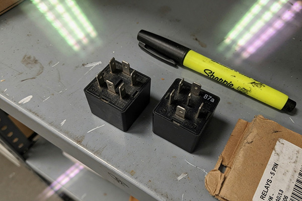
Contact Configurations: NO, NC, and Changeover
Understanding contact configuration is essential before ordering in quantity. Here are the standard types found in Chinese truck relays:
| Configuration | Abbreviation | Terminals | Function |
|---|---|---|---|
| Normally Open | NO (SPST-NO) | 30, 85, 86, 87 | Contact closes when coil is energized; open when coil is off |
| Changeover (NO + NC) | SPDT | 30, 85, 86, 87, 87a | Includes both a normally open (87) and normally closed (87a) contact; switches between them |
- A 4-pin relay is typically SPST-NO — it connects or disconnects a single circuit.
- A 5-pin relay is typically SPDT — it can switch between two circuits, or it can serve as an NO relay if only terminal 87 is wired.
The critical risk: a circuit designed for a changeover relay (SPDT) will not function correctly with a simple NO relay (SPST), even if the footprint matches. Conversely, installing a 5-pin SPDT relay into a 4-pin socket may leave the 87a terminal floating — which usually works but should still be verified.
Specs to Verify Before Every Order
Before confirming any relay purchase — especially in bulk — verify these five specifications against the OE number, truck model, or the relay currently installed:
- Coil voltage (12V or 24V DC)
- Contact current rating (continuous amps, with derating applied)
- Contact configuration (NO only, or NO + NC changeover)
- Terminal layout and numbering (matches the socket and wiring)
- Mounting and connector compatibility (tab orientation, bracket type)
When OE Numbers Are Your Best Friend
I cannot stress this enough: the OE number is the single most reliable way to ensure you are ordering the correct truck relay. Photographs help. Physical dimensions help. But the OE number eliminates ambiguity across coil voltage, current rating, and contact configuration simultaneously. When customers send us an OE number along with the truck model and chassis information, the match rate on relay orders is extremely high. When they send only a photograph or a description like "the relay near the fuse box," the risk of mis-selection increases significantly.
How Can a Simple Multimeter Check Save You From Unnecessary Relay Replacements?
Many maintenance teams replace relays by default when a circuit stops working. In our experience, a significant portion of "failed" relays are actually fine — the real fault lies elsewhere in the circuit. A basic multimeter check on the relay terminals takes less than two minutes and can confirm whether the relay itself is functional before you order a replacement.
To test a standard truck relay, use a multimeter to check coil resistance across terminals 85 and 86 (expect roughly 50–200 ohms for a 24V relay) and contact continuity across terminals 30 and 87 while the coil is energized. If the coil shows open-circuit resistance or the contacts fail to close when powered, the relay needs replacement. If both checks pass, the fault is likely elsewhere in the wiring or load.
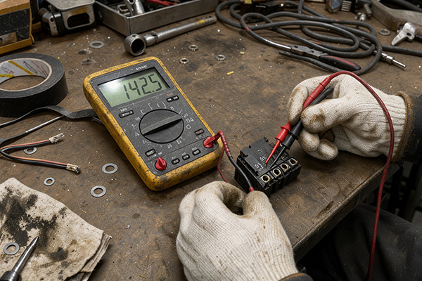
Step-by-Step Terminal Check Procedure
Here is the basic procedure we share with fleet maintenance teams and repair-shop customers. This applies to the standard ISO mini relay pinout (terminals 30, 85, 86, 87, and optionally 87a). Important: some Chinese-truck relays may use non-standard terminal numbering or unlabeled pins. Always check the markings on the relay body or refer to the OE documentation before testing.
Step 1: Identify the Terminals
- Terminal 85: Coil negative (ground side of the coil)
- Terminal 86: Coil positive (signal/trigger side)
- Terminal 30: Common contact (power input from battery or fuse)
- Terminal 87: Normally open contact (connects to load when relay is energized)
- Terminal 87a (if present): Normally closed contact (connected to terminal 30 when relay is de-energized)
Note: Some relays reverse 85 and 86 polarity conventions, or use different numbering entirely. If the relay has a wiring diagram printed on its body, follow that diagram.
Step 2: Check Coil Resistance
- Set your multimeter to the ohms (Ω) resistance setting.
- Place the probes on terminals 85 and 86.
- A healthy 24V truck relay coil typically reads between 50 and 200 ohms. A 12V relay coil reads lower, typically 30–100 ohms.
- Open circuit (OL / infinite resistance): The coil winding is broken. The relay is faulty.
- Very low resistance (near 0 ohms): The coil winding is shorted. The relay is faulty.
Step 3: Check Contact Operation
- With the relay removed from the vehicle, connect a 24V DC source (or 12V, matching the relay's coil voltage) to terminals 85 and 86. You should hear or feel the relay click.
- While the coil is energized, set your multimeter to continuity or low ohms.
- Test across terminals 30 and 87. You should see near-zero resistance (closed circuit).
- If the relay is SPDT (5-pin), also check that terminals 30 and 87a show open circuit while energized.
- De-energize the coil. Terminals 30 and 87 should now show open circuit. If 87a exists, terminals 30 and 87a should now show continuity.
Step 4: Interpret the Results
| Test | Expected Result | If Failed |
|---|---|---|
| Coil resistance (85–86) | 50–200Ω (24V) or 30–100Ω (12V) | Replace relay |
| Contact closed (30–87, coil energized) | Near 0Ω / continuity | Replace relay (contacts welded open or pitted) |
| Contact open (30–87, coil de-energized) | Open circuit / OL | Replace relay (contacts welded closed) |
| Click sound when coil energized | Audible click | If no click + coil resistance is normal, suspect mechanical jam — replace relay |
When the Relay Tests Fine
If the relay passes all checks, the problem lies elsewhere. Common culprits include:
- Blown fuse upstream of terminal 30
- Corroded or loose relay socket contacts — especially in humid or dusty environments
- Broken wire between the relay and the load
- Faulty control signal — the ECU or switch feeding terminal 86 is not sending voltage
- Bad ground on terminal 85
This simple diagnostic prevents unnecessary relay purchases and, more importantly, prevents installing a new relay into a circuit with an underlying fault that will just destroy the new relay too.
Frequently Asked Questions
Can I use a 12V relay in a 24V truck system?
No. Applying 24V to a 12V coil will overheat and burn out the coil winding, often within minutes. Always match the relay coil voltage to the specific circuit voltage — most Chinese heavy trucks (HOWO, SHACMAN, FAW) use 24V systems, but verify against the OE number or vehicle documentation.
How do I know if my truck relay needs a 4-pin or 5-pin type?
Check the relay socket on the truck. A 4-pin socket typically requires an SPST-NO relay (terminals 30, 85, 86, 87). A 5-pin socket typically requires an SPDT changeover relay (adds terminal 87a). The OE number is the most reliable way to confirm. Never assume based on socket shape alone — verify the circuit function.
Is it safe to use a higher-amp relay than the original?
Using a relay with a higher contact current rating than the original is generally acceptable and often advisable for inductive loads. The relay will simply have greater capacity than needed. However, the coil voltage, contact configuration, and terminal layout must still match exactly. A higher-amp relay does not compensate for a wrong coil voltage or incorrect pin arrangement.
Why does my new relay click but the circuit still doesn't work?
A clicking relay means the coil is energizing correctly, but clicking alone does not confirm the contacts are closing properly. The contacts may be defective, the relay socket may have corroded pins, or there may be a wiring fault downstream. Use a multimeter to check continuity across terminals 30 and 87 while the relay is energized and inspect the socket for corrosion.
How should I store relays in bulk to prevent damage?
Store truck relays in their original packaging or in sealed bags, in a dry environment away from direct sunlight and extreme temperatures. Humidity and dust are the primary enemies — corroded terminals increase contact resistance and cause intermittent failures after installation[9]. For long-term warehouse storage in tropical climates, consider moisture-absorbing desiccant packs inside sealed containers.
Conclusion
Getting truck relays right comes down to three verified specs: coil voltage matches the signal circuit, current rating includes a practical derating margin for real-world loads, and terminal configuration fits the actual circuit — not just the socket shape. A two-minute multimeter check on terminals 30, 85, 86, and 87 can confirm whether a relay is genuinely faulty before you order replacements. These steps apply across HOWO, SHACMAN, FAW, FOTON, and DONGFENG trucks, and they are the same checks we walk through with our customers every day during order consultations.
If you are sourcing truck relays in bulk — or any truck parts where correct specification matching matters — send us your OE numbers, truck models, and application details. We will confirm the exact match before your order ships. Reach out at grand@caanass.com or via WhatsApp: +86 19924698529 to start.
- [1]"Troubleshooting Relay Circuits: A Practical Guide for ...", https://www.allpcb.com/allelectrohub/troubleshooting-relay-circuits-a-practical-guide-for-electrical-engineers. When voltage applied to a relay coil exceeds its rated value, the resulting increase in current (I = V/R) produces excessive Joule heating (P = I²R) in the winding, which can degrade enamel insulation, cause inter-turn short circuits, and ultimately result in coil open-circuit failure (see standard electrical engineering references on electromagnetic relay operation). Evidence role: mechanism; source type: education. Supports: Applying voltage above a relay coil's rated value increases current proportionally (per Ohm's law), causing resistive heating that exceeds the coil's thermal design limits and degrades insulation. Scope note: Most relay coils tolerate modest overvoltage (typically up to 110–120% of rated voltage) without immediate failure; the severity depends on duration and thermal dissipation. ↩
- [2]"Semi Trucks Run on 24V for This Critical Reason", https://www.youtube.com/watch?v=LMhHlEIOHfo. Heavy-duty commercial vehicles worldwide, including those manufactured by Chinese OEMs such as Sinotruk (HOWO), SHACMAN, and FAW, typically employ 24-volt electrical systems to provide adequate power for larger starter motors and auxiliary systems; this convention follows the broader industry standard for trucks exceeding a certain gross vehicle weight. Evidence role: general_support; source type: encyclopedia. Supports: Heavy-duty commercial trucks, including Chinese brands, standardly use 24V electrical systems rather than the 12V systems found in light-duty vehicles. Scope note: General industry convention; specific model variants or auxiliary circuits may deviate from the 24V standard. ↩
- [3]"derating for eee-inst-002", https://snebulos.mit.edu/projects/crater/docs/engineering/EEE-parts-derating.pdf. Relay application guides from organizations such as the National Electrical Manufacturers Association (NEMA) and relay manufacturers' engineering handbooks recommend derating relay contact ratings by factors of 1.5× to 3× for inductive loads to account for inrush current surges and accelerated contact wear from arc suppression demands. Evidence role: expert_consensus; source type: research. Supports: Standard relay application engineering recommends derating contact current capacity when switching inductive loads due to inrush currents and arc erosion. Scope note: Specific derating factors vary by relay construction, arc suppression features, and load characteristics; the 1.5–2× range is a practical simplification. ↩
- [4]"Load bank", https://en.wikipedia.org/wiki/Load_bank. IEC 61810 (Electromechanical elementary relays) specifies that relay contact ratings are determined using resistive test loads at a reference ambient temperature of 23°C ± 5°C, meaning published ratings may not directly reflect performance under inductive loads or elevated temperatures encountered in vehicle applications. Evidence role: general_support; source type: institution. Supports: International relay testing standards specify resistive loads and controlled ambient temperatures as baseline conditions for contact current ratings. Scope note: Some manufacturers may test under additional conditions or publish application-specific ratings; the IEC standard represents the baseline methodology. ↩
- [5]"Analysis of factors influencing contact arc erosion under ...", https://ui.adsabs.harvard.edu/abs/2025AIPA...15d5201W/abstract. Contact welding occurs when current density at the contact interface generates sufficient localized heating to melt the contact material, fusing the contacts together; contact pitting results from material transfer during electrical arcing at make and break, progressively degrading the contact surface (Slade, P.G., 'Electrical Contacts: Principles and Applications,' CRC Press). Evidence role: mechanism; source type: paper. Supports: Excessive current through relay contacts causes localized melting (welding) and electrical arc erosion (pitting) that degrades contact surfaces. ↩
- [6]"THERMAL MANAGEMENT IN HEAVY VEHICLES", https://www.osti.gov/servlets/purl/12369. SAE International technical papers on commercial vehicle thermal management document under-hood ambient temperatures ranging from 80°C to over 125°C depending on proximity to the engine and exhaust system, operating load, and external climate conditions. Evidence role: statistic; source type: paper. Supports: Under-hood temperatures in commercial vehicles can reach or exceed 80°C, particularly near the engine block and exhaust components. Scope note: Exact temperatures vary significantly by vehicle design, sensor placement, and operating conditions; 80°C represents a moderate rather than extreme under-hood measurement. ↩
- [7]"Relay Contact Bounce: Understanding and Mitigation ...", https://www.allpcb.com/allelectrohub/relay-contact-bounce-understanding-and-mitigation-techniques. Studies on relay reliability in automotive environments demonstrate that mechanical shock and vibration can cause momentary contact separation (bounce), generating micro-arcs at each bounce event that cumulatively erode contact material and increase contact resistance over the relay's service life (see SAE technical papers on electrical component vibration endurance). Evidence role: mechanism; source type: paper. Supports: Mechanical vibration in vehicle environments can induce relay contact bounce, producing repetitive micro-arcs that accelerate contact surface erosion. Scope note: The severity of vibration-induced contact bounce depends on relay construction quality, mounting method, and the specific vibration spectrum of the vehicle application. ↩
- [8]"Relays", http://faculty.ccp.edu/faculty/dreed/AT121/at121files/relays.htm. The ISO 7588 standard defines the dimensions, terminal layout, and performance requirements for miniature automotive relays (commonly called 'ISO mini relays'), establishing the widely used 4-pin and 5-pin configurations with terminals designated 30, 85, 86, 87, and 87a. Evidence role: definition; source type: institution. Supports: The ISO mini relay form factor is defined by international standards governing automotive relay dimensions and terminal arrangements. Scope note: Some relay manufacturers, particularly in aftermarket or regional markets, may deviate from strict ISO 7588 compliance while maintaining physical compatibility. ↩
- [9]"Humidity Affects Electronics in Desiccator Cabinets", https://www.cleatech.com/humidity-electronic-components-desiccator-cabinets/. Research on electrical contact reliability demonstrates that elevated humidity accelerates oxidation and formation of resistive surface films on metallic contacts, particularly on tin and copper alloy terminals common in automotive relays, leading to increased contact resistance and intermittent circuit failures (see IPC J-STD-033 for moisture sensitivity classification of electronic components). Evidence role: mechanism; source type: research. Supports: Humidity exposure promotes oxidation and corrosion of relay terminal surfaces, increasing contact resistance and causing intermittent electrical failures. Scope note: IPC standards primarily address semiconductor and PCB component moisture sensitivity; the corrosion mechanism is analogous but relay-specific storage standards may differ. ↩